

Getting back to basics is still important in plastics design, despite the sophisticated design aids now available.
Increasingly, structural parts in plastic are designed and manufactured with the aid of computer systems for part design, tool design, polymer flow and stress analysis. If the plastic is much more than a space filler, many considerations will come into play. How will the plastic flow, and what about shrinkage? Most importantly, will the part have sufficient strength and stiffness to perform in service?
Search for plastics by material properties
With Prospector's Property Search, search by properties to effectively and efficiently find the right plastics for your project.
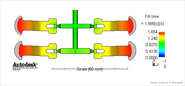
CAD systems are becoming increasingly sophisticated, with modules which assist a designer using plastics. Flow simulation programs will model the stresses on the part during moulding, and finite element analysis will model the part in service. These tools enable the designer to make iterative modifications to part and tool long before the part ever sees the light of day. In this way, the designer can get the part to market more quickly and eliminate modification costs at a later stage in the process.
When designing a structural part in plastics, it is important to spend time upfront selecting the right material and designing the part to get the best out of the material. A materials selection system such as UL Prospector will enable the designer to experiment with candidate materials with different properties in this virtual space.
But equally, many parts are designed without ready access to these best-in-class design tools. Very often, design is conducted back to front, with the geometry done first and then producing a tool for, let’s say, injection moulding, and then worrying about what material should be used.
Either way, it is good practice to be competent in the basics of plastic part design, which now date back two generations. Compare that with the thousands of years of experience we have with metals.
Time dependent properties
For most designs in metals, there is no need to worry about the effects of time, temperature or environment. But plastics are a different story - they come in a bewildering variety and are more complicated. They can creep and shrink with time; in most cases, their properties change over the temperature range of everyday life; and they may be affected by common household and industrial materials.
Because the basic design rules for plastics are essentially an extension of the rules of physics, they have not changed since the advent of time, or at least not since 1960! This means that there are many good sources of design guidance available in print or on the web. They are as valid now as they were when they were first written. They cover the basics of polymer moulding, and design techniques such as the use of ribs and bosses (see below). And having mastered these basics of polymer design, a wealth of design information also exists to help with components such as integral hinges, bearings and gears.
Amazingly, there are now over 100 distinct generic types of polymer. On top of that, advanced techniques with catalysts and compounding are creating new alloys, blends and molecular forms. We can modify the properties of all of these materials via control of molecular weight and with additives such as reinforcements. The number of different grades of plastics materials available to the designer now exceeds 50,000.
Good design must combine concept with functionality. Unless the two are considered together, the result will be an article that cannot be made economically or one that fails in use. This is particularly important for plastics.
While it is vital to choose the right material for the job, it is equally important to adapt the details of the design to suit the characteristics of the material and the limitations of the production process.
Shells not solids
Parts that might be made as solid shapes in traditional materials must be formed quite differently in plastics. Moulded plastics do not lend themselves to solid forms: firstly, plastics are processed with heat but are poor conductors of heat. This means that thick sections take a very long time to cool and so are costly to make. The problems posed by shrinkage are severe.
Secondly, engineering plastics are expensive and only high-speed and net-shape production methods make mouldings viable.
Plastic wall thickness
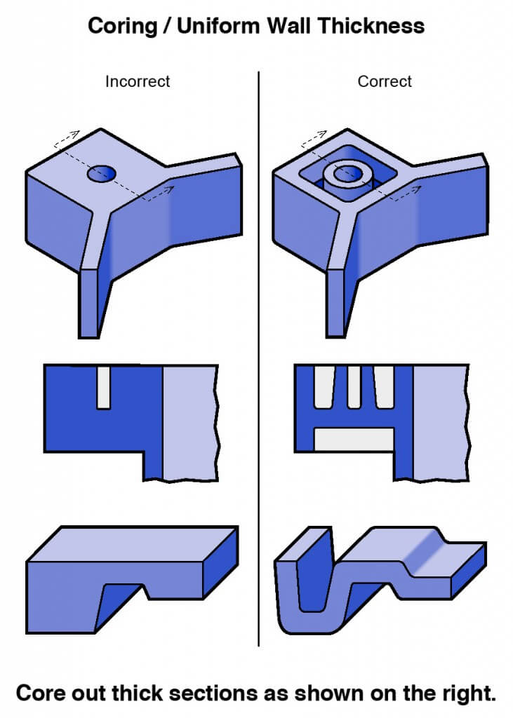
Thick sections waste material and are simply uneconomic. So solid shapes that would do the job well in wood or metal must be transformed to a 'shell' form in plastics. This is done by hollowing out or 'coring' thick parts so you are left with a component which, regardless of complexity, is composed essentially of relatively thin walls joined by curves, angles, corners, ribs, steps and offsets. As far as possible, all these walls should be the same thickness.
The wall must be thick enough to do its job - it must be strong and stiff enough, but also thin enough to be affordable. It must also be thin enough to cool quickly, yet thick enough to allow efficient mould filling. If the material is inherently strong or stiff, the wall can be thinner. As a general guide, wall thicknesses for reinforced materials should be 0.75 to 3mm, and for unfilled materials 0.5 to 5mm.
Ideally, the entire component should be a uniform thickness - the nominal wall thickness. In practice that is rarely possible; there must be some variation in thickness to accommodate functions or aesthetics. It is very important to keep this variation to a minimum.
A plastics part with thickness variations will experience differing rates of cooling and shrinkage. The result is likely to be a part that is warped and distorted, one in which close tolerances become impossible to hold.
Where variations in thickness are unavoidable, the transformation between the two should be gradual and not sudden. Instead of a step, a ramp or curve is used to move from thick to thin.
Properly designed corners will make a big difference to the quality, strength and dimensional accuracy of a moulding. But there is another benefit too. Smooth curved corners help plastic flow in the mould by reducing pressure drops in the cavity and minimising breakup in the molten plastic flow-front.
Adding plastic ribs
When the normal wall thickness is not stiff enough or strong enough to stand up to service conditions, rather than making the whole wall thicker, the part can be strengthened by adding ribs. The principle is similar to that used in steel girders, where 'I' and 'T' sections are almost as rigid as solid beams, but are only a fraction of the weight and cost.
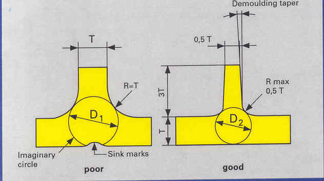
A thicker section is inevitable where the rib joins the main wall. To avoid sink marks, this thick region must be kept to a minimum, but if the rib is too thin, it will have to be made deeper to give adequate rigidity. Then it may buckle under load and the mould becomes difficult to machine and fill. Ribs filled under high injection pressure tend to stick in the mould.
The fillet radius must not be made too small either, or it will not succeed in reducing stress concentrations where the rib joins the main wall. Ideally, the fillet radius should not be less than 40 percent of the rib thickness. The ribs themselves should be between half and three-quarters of the wall thickness. Even then, the high end of this range is best confined to plastics that have a low shrinkage factor and are less prone to sink marks.
Boss mountings
The boss is one of the most useful design elements of a plastics moulding. It is used whenever a mounting point, a location point, a reinforcement around a hole, or a spacer are needed. Bosses don't have to be, but are usually cylindrical because that is the easiest form to machine in the mould; it is also the strongest shape to have in the moulded part. The boss may receive an insert, a screw, or a plain shaft either as a slide or a press fit.
Depending on its use, it may have to stand up to a whole combination of forces – tension, compression, torsion, flexing, shear and bursting - so it must be designed accordingly.
The general design rules are the same as for ribs and walls. The boss can be thought of as a special case of a rib; one that is wrapped round in the form of a tube. An 'ideal' boss, designed according to rib rules, would not produce sink marks or stick in the mould but unfortunately the tubular form of the boss would not be strong enough in most cases. In real life, most bosses break some design rules by necessity and the design is a compromise between sink marks and functionality.
Rigidity is the simplest aspect of boss design. This can be achieved by supporting the boss with buttress ribs, and often by linking the boss to a side wall. The support ribs can be designed to normal rib rules so that sink marks and stress points are avoided.
The views, opinions and technical analyses presented here are those of the author or advertiser, and are not necessarily those of ULProspector.com or UL Solutions. The appearance of this content in the UL Prospector Knowledge Center does not constitute an endorsement by UL Solutions or its affiliates.
All content is subject to copyright and may not be reproduced without prior authorization from UL Solutions or the content author.
The content has been made available for informational and educational purposes only. While the editors of this site may verify the accuracy of its content from time to time, we assume no responsibility for errors made by the author, editorial staff or any other contributor.
UL Solutions does not make any representations or warranties with respect to the accuracy, applicability, fitness or completeness of the content. UL Solutions does not warrant the performance, effectiveness or applicability of sites listed or linked to in any content.
Hi Andy,
simple and great. Allow me just one comment about ribs:
All fine with the 60 – 70% reduction in thickness for avoiding the sink. But:
not identic thicknesses bend the whole piece during cooling and shrinkage process.
In all literature there is much too less emphasis on this matter. Many parts show a huge overall tendancy to bend due to the different thicknesses of the ribs.
WEP
Hello,
In the article, when it says “The ribs themselves should be between half and three-quarters of the wall thickness”.
I can’t agree with it. In my experience with a lot of plastic parts. If we work with half and three-quarters of Wall thickness, we are going to have problems of sink marks. I would work between 1/3 and half Wall thickness.
But, You have to remind that It’s only my opinión.
Best regards
Very interesting article
I would like to be content
I agree with your comment here. To ensure minimal shrinkage, rib thickness (t) should be no more than half the wall main thickness (T) and ideally one third.
The rib image in the article I believe is also misleading; the rib fillet should be no more than half the rib thickness (t/2) and not half the main wall thickness (T/2).