

By Protomold – Nobody’s Faster In The Short Run.®
“Flaps 10 degrees………check, cabin air intake………check, landing light………check.”
Ever dream about being a pilot running through your preflight checklist with your co-pilot? Well, now as a designer, you can have almost as much fun when you design plastic parts using the Protomold Plastic Part Design Checklist. You too can be confident you won’t miss a single aspect of parts design when you use this handy resource tool.
Like a pilot’s preflight routine, our checklist below is a handy reminder of some of the considerations to keep in mind when you’re designing injection molded plastic parts.
And, in addition to our checklist, we’ve cataloged dozens of tips that can aid in making your parts easier to manufacture, lighter, stronger and offer improved performance. Each tip is chock full of great manufacturability pointers, including coring out, preventing sink, drafting for easy ejection, adding text, and more. Some of these useful design tips are referenced in the designer checklist; or you can download our complete Design Tip compilation volumes here.
Also, you can access ProtoQuote® automated design analyses, which can help to identify potential design problems once a 3D CAD model has been submitted. These free services allow you to quickly see issues that are easy to overlook. Our suggestions and recommended design modifications are returned to you within one day of submitting your part.
Try our Checklist! It’s a practical tool that allows you, the designer, to spot potential issues and correct them beforehand.
________________________________________________________________________________________________________________________
PLASTIC PART DESIGN CHECKLIST:
Designing with Protomold in mind
 |
Design Considerations
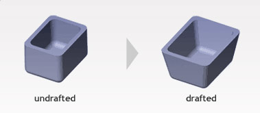
Are the cores and holes drafted towards the ejector pin side (low cosmetic side) of my part?
YES
Does my part design include sufficient draft for part removal from mold?
YES — We strongly advise using at least 0.5 degrees on all “vertical” faces.
Do I need to add draft to my design?
MAYBE — For aluminum molds, increments of .5 degrees (shallow features) to 3 degrees (deep features) should be added. A good rule of thumb is 1 degree per inch depth including cam/side pull cores.
 |
Does my part have a wall thickness that is greater than .040″ and under .180″?
YES
NO — Parts under .040″ may produce a part that has shorts, voids, weak knit lines; parts over .180″ may have excessive sink, internal voids, warp, poor texture pick-up.
—————————————————————————————————————————————————————————————————————-
Materials
What do I need to consider when selecting a material that is best for my design?
- Selection of the proper material is crucial to part production. Designers should consider the mechanical characteristics, molding properties, and cost of the resin used.
Learn more about material selection. - Uniform wall thickness for all resins is the best place to start.
- Glass filled resins are more likely to warp.
—————————————————————————————————————————————————————————————————————-
Dimensions
Does my part have two dimensions that are larger than .25″ and less than one of the following? (Dimensions (in mold) = X x Y x Z (depth of part))
- 30.5″ X 13.5″ X .25″
- 28.5″ X 11.5″ X 1″
- 26.5″ X 9.5″ X 2″
- 24.5″ X 7.5″ X 3″
YES — proceed to Volume
NO — My part is over 3″.
My part is over 3″ deep, is my parting line in the middle of the part?
YES
NO — Protomold may not be able to mold your part
—————————————————————————————————————————————————————————————————————-
Volume
Does my part have a volume greater than .005 in³?
YES — proceed
NO — Protomold may not be able to mold your part
Does my part have a volume less than 59 in³?
YES — proceed
NO — Protomold may not be able to mold your part
—————————————————————————————————————————————————————————————————————-
Surface Area
Does my part have a surface area of less than 175 square inches?
YES — proceed
NO — Protomold may not be able to mold your part
—————————————————————————————————————————————————————————————————————-
Geometry
Is it a straight pull mold?
YES — proceed
NO — Off angle geometry may need to be modified or cams/side actions need to be applied
I DON’T KNOW
—————————————————————————————————————————————————————————————————————-
Undercuts
Are the undercuts located towards the outside of my part?
YES — Proceed to next question, Protomold may be able to use cams/side actions to mold the undercut
NO — Pass through cores or filling in the undercut geometry will be required. Protomold can certainly mold your prototype parts, however may not be able to mold your production parts. You could cut the undercut geometry with a secondary operation for testing or low volume production.
Is the undercut on my part less than one 8.419″ X 2.377″ X 2.900″? (Dimensions (in mold) = Horizontal x Vertical x Depth of cam pull)
YES — Protomold will use cam/side action to mold the feature
NO — Can you use sliding shut offs?
The views, opinions and technical analyses presented here are those of the author or advertiser, and are not necessarily those of ULProspector.com or UL Solutions. The appearance of this content in the UL Prospector Knowledge Center does not constitute an endorsement by UL Solutions or its affiliates.
All content is subject to copyright and may not be reproduced without prior authorization from UL Solutions or the content author.
The content has been made available for informational and educational purposes only. While the editors of this site may verify the accuracy of its content from time to time, we assume no responsibility for errors made by the author, editorial staff or any other contributor.
UL Solutions does not make any representations or warranties with respect to the accuracy, applicability, fitness or completeness of the content. UL Solutions does not warrant the performance, effectiveness or applicability of sites listed or linked to in any content.