

In materials and component testing the range of applications where extensometers are used is extremely diverse. As a result, the technical requirements for these devices are multifaceted, and means that there is no single device which satisfies all needs. As a pioneer and global leader in modern extensometry, the Zwick Roell Group believes that it offers its customers the widest range of technical advice, products, and solutions.
Specimen properties which influence the choice of extensometer
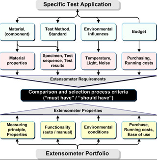
The requirements for an extensometer are determined primarily by the characteristics of the material to be tested. This includes its shape and dimensions, test requirements, and the formal Standards which must be met. These define the gauge length, accuracy, test sequence, and environmental conditions.
Having said this, the right choice of extensometer cannot be limited to the basic material characteristics such as specimen dimensions, stiffness, strength and plasticity alone. It is also necessary to decide whether an extensometer can be connected directly to the specimen without influencing the load measurement or mechanically damaging the specimen itself.
Very thin specimens such as foils can be sensitive to clamping forces, whilst very small wire specimens do not provide enough visible area for reliable non-contact measurements.
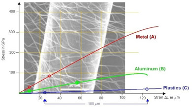
A high stiffness in the initial extension range, followed by high plasticity traditionally requires more than one extensometer. The first measures small strains (typically up to 5 mm) very accurately in the elastic range, and the second measures very high extensions (typically ≥ 500 mm).
Specimen with very smooth surfaces, or made of transparent materials are not suitable for non-contact measurements without first fixing measuring marks onto the surface of the specimen.
One very important consideration is the behaviour when the specimen fails. Metals and hard plastics will slip through the knife edges of a contact extensometer without damaging them, and rotatable knife edges should be used to further reduce the risk of damage even if the surface of the specimen is particularly rough.
High extension or flexible specimens can damage or destroy the knife edges and even the extensometer itself due to whiplash, splintering, or de-lamination of specimens (for example steel rope). For these applications non-contact measurement is a must.
Criteria for accurate measurements:
Measurement travel (range) and gauge length
With contact type measuring extensometers, the measurement travel is normally an engineered and fixed value which is dependent upon the range of the measurement transducer and, with fulcrum hinged sensor arms, the leverage ratio. The initial gauge length is set manually with fixed steps or automatically over a defined range.
Non-contact extensometers that use a video camera must have the field of view larger than the required range plus the initial gauge length. Since the specimen portions which are outside the gauge length, and the machine components themselves deform in the direction of loading, the position of the measuring marks on the specimen changes during the test. For extension and/or gauge lengths which are expected to be outside of the field of view then the objective lens must be changed or the distance between the specimen and the video camera must be increased. All these actions decrease the measuring accuracy, and in addition, every changed measurement configuration must be adjusted and calibrated.
Measurement accuracy
“Accuracy” is a commonly used, qualitative term. To qualify the integrity of a measured signal Standards use quantitative terms such as “resolution”, “deviation” or “uncertainty” and definitive values are given for these. Requirements for the accuracy of extension measurements are normally given in application specific test requirements and International Standards. Many test Standards, for example, tensile test on metals [1] and plastics [2] refer to Standards for calibration of extension measurement systems and the required accuracy classes [3,4] contained therein.
Ergonomics and economy
Devices which are easy to set-up and sequences which can be automated reduce personnel time and effort and at the same time improve the quality of the test results because subjective influences are minimized. Higher initial acquisition costs can be quickly amortized, especially when the extensometer can be used for a wide range of applications.
When using a video extensometer the time and costs for marking the specimen must also be considered as well as any potential human error introduced in attaching or aligning the marks.
Contact type measurement extensometer:
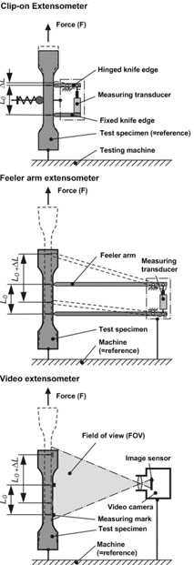
Clip-on extensometers are, as the name implies, mounted directly onto the specimen. The mechanical parts which transfer extension, via knife edges, from the specimen to the internal transducer are short and stiff. There is practically no relative movement between the specimen and the extensometer and for this reason the measurement accuracy is exceptionally high.
The range of a clip-on extensometer is limited to a few millimetres and it applies a load directly to the specimen. Some extensometers are available with counter-balance weight and double-sided measuring systems are used to compensate for superimposed bending stresses. The application and removal is normally manual, however, to minimise setting errors certain products are equipped with motorised application and removal systems.
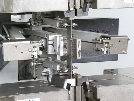
Feeler arm extensometers offer the major advantage of automatic operation and a large measurement range with high measurement accuracy and are suitable for many different applications. Precision designs with a very smooth and balanced mechanical operation apply minimum loading to the specimen (as little as the measurement marks used for non-contact extensometers). Since the feeler arms are in contact with both sides of the specimen, superimposed bending strains are largely compensated.
Clip-on and feeler arm extensometers are in direct mechanical contact with the specimen via knife edges which are perpendicular to the gauge length. The extremely small contact force from the knife edges can cause a microscopic indentation into the specimen surface which gives a light form-fit and thereby a precisely positioned contact point. This is an important factor for the large measurement accuracy and small scatter band width of the measured values. Because of the direct contact with the specimen, feeler arm extensometers can be damaged or even destroyed by whip-lash at the failure point of high elasticity / high extension specimens.
Non contact extensometers (video and laser scanning)
The main advantage of non-contact video and laser scanning extensometers is that they can be used up to break without damage even when testing specimens that exhibit whiplash. They require measurement marks to be attached to the specimen which are optically distinct from the surrounding area of the specimen.
The measurement marks are clipped, tacked, or glued onto the specimen, or the specimen is marked with a coloured pen. In every case, this introduces additional sources of error as the marks can become indistinct, move, or fall off the specimen surface as it deforms during loading. The application of the measurement marks is also an additional process by the operator and can introduce higher costs as well as inaccuracies to the test results.
The position of the measurement marks on the specimen is evaluated by software algorithms which determine a certain area around an Optical Centre Point. This becomes the gauge length and as the specimen is loaded the movement of the marks is converted to extension values. Special lighting for surface or background illumination of the specimen optimises the contrast to the measurement mark. During the deformation of the specimen, the lighting changes on the measurement marks as well as specimen and surrounding influences (reflections etc.) can influence the optical centre point. This is often the cause of scatter in the test results.
Non contact extensometers (laser interferometry)
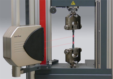
The latest extensometer from Zwick, the laserXtens, is a non contacting device which does not require measurement marks. It uses the unique structure of a specimen´s surface as a “fingerprint” to generate a virtual measurement mark. Laser light directed on these measurement positions is reflected in various directions corresponding to the surface structure and creates a specific pattern of speckles. Selected measurement points are constantly followed and converted to direct extension values. The change in the surface structure, which is the basis of the speckle pattern, is continuously evaluated during specimen deformation.
Summary
Contact type extensometers measure extension extremely accurately and are very cost effective. However, clip-on extensometers require much more manual intervention and without care can introduce scatter in the test results. Feeler arms extensometers offer extremely high accuracy, excellent repeatability, and ease of use due to fully automatic operation which includes the setting of variable gauge lengths.
Non contact extensometers are required when the specimen is sensitive to notching knife edges or when the extensometer might be damaged at specimen break. They are also still relatively expensive and time consuming to set up and calibrate especially when testing different specimen types.
In short, there is no such device as a universal extensometer. The large range of applications demands various devices with different functions and characteristics, and the extensometer must be selected for each application.
Users of Zwick testing equipment benefit from the wide range of extensometers available, as well as expert advice and consultation together with the possibility to carry out pre-testing in the applications laboratory before purchase to make sure that the optimum device is chosen for each testing application.
Literature
1 DIN EN 1002 Metalic Materials – Tensile tests
2 DIN EN ISO 527 Thermo-plastics and duro-plastics – Determination of Tensile Characteristics
3 DIN EN ISO 9513 Calibration of extension measurement systems for testing with single axis loading
4 ASTM E 83-02 Standard Practice for Verification and Classification of Extensometer System
The views, opinions and technical analyses presented here are those of the author or advertiser, and are not necessarily those of ULProspector.com or UL Solutions. The appearance of this content in the UL Prospector Knowledge Center does not constitute an endorsement by UL Solutions or its affiliates.
All content is subject to copyright and may not be reproduced without prior authorization from UL Solutions or the content author.
The content has been made available for informational and educational purposes only. While the editors of this site may verify the accuracy of its content from time to time, we assume no responsibility for errors made by the author, editorial staff or any other contributor.
UL Solutions does not make any representations or warranties with respect to the accuracy, applicability, fitness or completeness of the content. UL Solutions does not warrant the performance, effectiveness or applicability of sites listed or linked to in any content.