By Vishu Shah, Consultek
Strain Gauge Method
The electrical resistance strain gauge method is the most popular and widely accepted method for strain measurements. The strain gauge consists of a grid of strain-sensitive metal foil bonded to a plastic backing material. When a conductor is subjected to a mechanical deformation, its electrical resistance changes proportionally. This principle is applied in the operation of a strain gauge. For strain measurements, the strain gauge is bonded to the surface of a part with a special adhesive and then connected electrically to a measuring instrument. When the test part is subjected to a load, the resulting strain produced on the surface of the part is transmitted to the foil grid. The strain in the grid causes a change in its length and cross section, and produces a change in the resistivity of the grid material. This change in grid resistance, which is proportional to the strain, is then measured with a strain gauge recording instrument. In using strain gauges for failure analysis, care must be taken to test the adhesives for compatibility with particular plastics to avoid stress-cracking problems.
Residual or molded-in stresses can be directly measured with strain gauges using the hole drilling method. This method involves measuring a stress at a particular location, drilling a hole through the part to relieve the frozen-in stresses, and then remeasuring the stress. The difference between the two measurements is calculated as residual stress.
Chemical Method
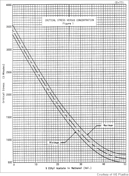
Most plastics, when exposed to certain chemicals while under stress, show stress cracking. This phenomenon is used in stress analysis of molded parts. The level of molded-in or residual stress can be determined by this method. The part is immersed in a mixture of glacial acetic acid and water for 2 min at 73°F and later inspected for cracks that occur where tensile stress at the surface is greater than the critical stress. The part may also be externally stressed to a predetermined level and sprayed on with the chemical to determine critical stresses. Stress cracking curves for many types of plastics have been developed by material suppliers. If a defective product returned from the field appears to have stress-cracked, similar tests should be carried out to determine molded-in stresses as well as the effect of external loading by simulating end-use conditions. Failures of such types are quite common in parts where metal inserts are molded-in or inserted after molding. Three other tests, the stain-resistance test, solvent stress-cracking resistance, and environmental stress-cracking resistance (ESCR), are also employed to analyze failed parts.
 Heat Reversion Technique
All plastics manufacturing process introduce some degree of stress in the finished product. The stresses in molded parts are commonly referred to as molded-in (residual) stresses. By reversing the process, by reheating the molded or extruded product, the presence of stress can be determined. The test is conducted by simply placing the entire specimen or a portion of the specimen in thermostatically controlled, circulating air oven and subjecting to a predetermined temperature for a specified time. The specimens are visually examined for a variety of attributes. The degree and severity of warpage, blistering, wall separation, fish-scaling and distortion in the gate area of molded parts indicate stress level. Stresses and molecular-orientation effects in the plastic material are relieved, and the plastic starts to revert to more stable form. The temperature at which this begins to occur is important. If changes start below the heat distortion temperature of the material, high levels of stress and flow orientation are indicated. The test has been significantly improved by new methods including the attachment of strain gages to critical regions of the part to carefully monitor initial changes in the shape. ASTM F1057 describes the standard practice for estimating the quality of extruded PVC pipe by the heat reversion technique.
Microtoming
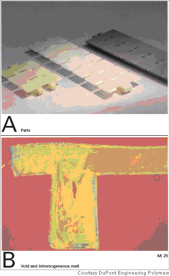
Microtoming is a technique of slicing an ultra thin section from a molded plastic part for microscopic examination. Biologists and metallurgists have used this technique for years, but only in the last decade has this technique been used successfully as a valuable failure analysis tool. Courtesy DuPont Engineering Polymers
 Microtoming begins with the skillful slicing of an 8-10 m-thick section from a part and mounting the slice on a transparent glass slide. The section is then examined under a light transmission microscope equipped with a polarizer for photoelastic analysis. A high power (1000x) microscope, which will permit photographic recording of the structure in color, is preferred. By examining the microstructure of a material, much useful information can be derived. For example, microstructural examination of a finished part that is too brittle may show that the melt temperature was either nonuniform or too low. The presence of unmelted particles is usually evident in such cases. Another reason for frequent failures of the injection molded part is failure to apply sufficient time and pressure to freeze the gates. This causes the parts to be underpacked which creates center-wall shrinkage voids. Voids tend to reduce the load-bearing capabilities and toughness of a part through the concentration of stress in a weak area. Contamination, indicated by abnormality in the microstructure, almost always creates some problems. Contamination caused by the mixing of different polymers can be detected through such analysis by carefully studying the differences in polymer structures. Quite often, poor pigment dispersion also causes parts to be brittle. This is readily observable through the microtoming technique. In order to achieve optimum properties, additives such as glass fibers and fillers must disperse properly. Microtoming a glass fiber-reinforced plastic part reveals the degree of bonding of the glass fiber to the resin matrix as well as the dispersion and orientation of glass fibers. Molded-in stresses as well as stresses resulting from external loading are readily observed under cross-polarized light because of changes in birefringence when the molecular structure is strained. Microtoming technique can also be applied to check the integrity of spin and ultrasonic or vibration welds.
Mechanical Testing
Defective product returned from the field is often subjected to a variety of mechanical tests to determine integrity of the product. Two basic methods are employed. First one involves conducting mechanical tests such as tensile, impact or compression on actual part or a small sample cut out from the part. The test results are then compared to the test results obtained from the retained samples. The second method requires grinding-up the defective parts and either compression or injection molding standard test bars and conducting mechanical tests. The test results are compared to the published data for the virgin material. The amount of material available for molding the test bars quite often precludes injection molding. The test data obtained from compression-molded samples are generally lower than injection molded samples. Fatigue failure tests such as flexural fatigue or tensile fatigue can be employed to determine premature failure from cyclic loading. Mechanical tests are discussed in detail in Chapter 2 of this book.
Thermal Analysis
Thermal Analysis techniques such as TGA, TMA, and DSC are used extensively in failure analysis.
Nondestructive Testing (NDT) Techniques
NDT techniques are useful in determining the flaws, discontinuities and joints.
About the Author
| Vishu Shah Consultek Consulting Group www.consultekusa.com www.plasticexpertwitness.com www.theplasticfailureanalysis.com |
Vishu H. Shah is President of Consultek Consulting Group, a technical and management consulting firm for plastics professionals. His 35 years of extensive practical experience in plastics Industry includes positions as president and cofounder of Performance Engineered products, Senior Plastics Engineer of Rain Bird Corporation and Nibco Inc. His areas of expertise include product design, processing, automation, materials, rapid prototyping, tooling, failure analysis and testing. His industry related experience ranges from developing and training personnel, writing standard operating procedures, obtaining certifications, negotiating major contracts, and developing business plans for growth and expansion as a custom Injection Molder, Providing technical services to engineering and quality assurance staff in the area of material selection, product development, processing, tooling design, and inspection techniques, setting up and running PVC compounding operation, developing formulations, and automation projects to serving as expert witness for legal community. |
The views, opinions and technical analyses presented here are those of the author or advertiser, and are not necessarily those of ULProspector.com or UL Solutions. The appearance of this content in the UL Prospector Knowledge Center does not constitute an endorsement by UL Solutions or its affiliates.
All content is subject to copyright and may not be reproduced without prior authorization from UL Solutions or the content author.
The content has been made available for informational and educational purposes only. While the editors of this site may verify the accuracy of its content from time to time, we assume no responsibility for errors made by the author, editorial staff or any other contributor.
UL Solutions does not make any representations or warranties with respect to the accuracy, applicability, fitness or completeness of the content. UL Solutions does not warrant the performance, effectiveness or applicability of sites listed or linked to in any content.


