Based on Dr. Stefan Glaser’s work on Predicting Reinforced Plastic Material Performance.
By Dr. Emile Homsi
Design engineers have traditionally used Finite Element Analysis (FEA) to predict reinforced plastic material performance. However, the technique presumes uniform distribution of fiber throughout the molded part. Generally, mold filling parameters and part geometry variations greatly affect the fiber distribution and orientation and, therefore, the part’s resulting mechanical and thermal performance. To be sure, designers apply safety factors to their assumptions of material strength to help design against part failure. In some cases, though, the resulting designs can be too conservative – leading to added material cost – or simply marginal, requiring extra validation testing and development delays.
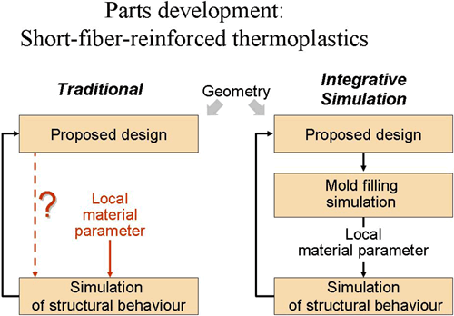
Barriers to a complete and accurate picture of part for reinforced plastic material performance
The molding process influences the orientation of reinforcing fibers, which affects mechanical properties such as part stiffness, tensile strength and resistance to heat distortion. Fiber orientation within the molded part is non-uniform, resulting in varying material properties in different directions (anisotropy). Instead of the uniform, isotropic display of strength and properties in all directions previously assumed by FEA, more accurate FEA models should incorporate realistic non-uniform fiber orientation and the anisotropic, non-uniform properties directly related to variations in fiber orientation and concentration.
Typically, analysts use a safety factor to compensate for the gap in knowledge of how material properties vary in a fiber-reinforced plastic part. However, the safety factor neglects the part’s fiber orientation-induced anisotropy, accounting instead for its effect by degrading to some degree the strength and modulus values determined by tensile testing. Unfortunately, this approximation overestimates properties in some areas and underestimates them in others.
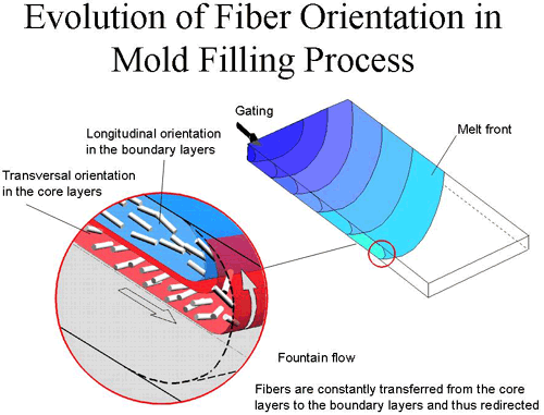
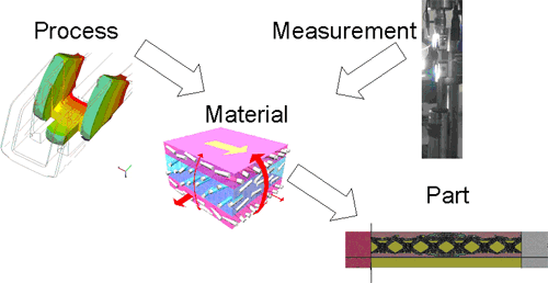
Evolution of Fiber Orientation in Mould Filling Process
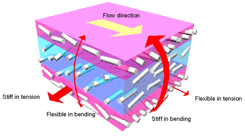
Mechanical behaviour of anisotropic layered shells
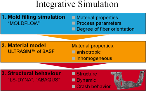
The three steps of integrative simulation
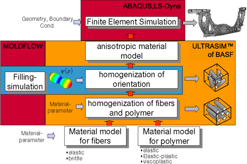
BASF has developed an integrative simulation method to overcome the limitations of prior predictive models. In the first step, the fiber orientation within the part is determined via mold filling simulation with MOLDFLOW, the most widely used commercial mold filling simulation software. The computation takes into account the properties of the molding compound – including melt viscosity and fiber content – as well as such process parameters as injection speed and holding pressure.
In the second step, information gained about fiber orientation in the molded state is then used in a non-linear, anisotropic material model – ULTRASIM™, BASF’s proprietary software module. With the help of this model (and software module), designers can calculate mechanical properties of the resin/fiber composite from the various fiber orientations as well as the separate mechanical properties of the resin matrix and fibers.
ULTRASIM™ is very flexible, allowing the use of various material/analysis models. The beauty of the software is that the designer doesn’t have to calculate the material properties; they are determined by the process.
In the third step, designers perform a structural analysis to predict the precise failure modes of the part, using either LS-DYNA or ABAQUS — two common commercial finite-element software packages, to which BASF’s material model extension has been added.
New “ULTRASIM™” software module links filling simulation and structural analysis of part
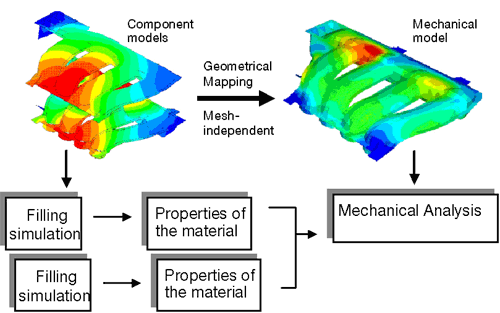
The ULTRASIM™ module factors fiber-orientation data into the structural analysis. Fiber orientations determined from the mold filling simulation transfer via the ULTRASIM™ software to the finite element mesh of the part’s structural model, thereby establishing a new set of local material parameters. Because the transfer is purely geometrical, the data can apply to a variety of meshes. User-defined functions allow inclusion of non-linearity and complex failure modes in the description of the material – something previously not possible. Efficient management of the vast quantity of input data required is fundamental to the whole process.
ULTRASIM™ thus forms a link between mold filling simulation, the resulting fiber orientation, and the structural analysis of the part. The results can be dramatic. In some cases, BASF’s ULTRASIM™ has already helped customers entirely eliminate, or reduce the time required for, a prototype stage or stages.
The views, opinions and technical analyses presented here are those of the author or advertiser, and are not necessarily those of ULProspector.com or UL Solutions. The appearance of this content in the UL Prospector Knowledge Center does not constitute an endorsement by UL Solutions or its affiliates.
All content is subject to copyright and may not be reproduced without prior authorization from UL Solutions or the content author.
The content has been made available for informational and educational purposes only. While the editors of this site may verify the accuracy of its content from time to time, we assume no responsibility for errors made by the author, editorial staff or any other contributor.
UL Solutions does not make any representations or warranties with respect to the accuracy, applicability, fitness or completeness of the content. UL Solutions does not warrant the performance, effectiveness or applicability of sites listed or linked to in any content.


