

Paid content by BASF
By Chul Lee, BASF
This is the fourth in a series of five articles on Snap-Fit design presented by BASF Engineering Plastics. Our intent is to help design engineers achieve better results through the use of improved principles and procedures for snap-fit design, application, processing and fabrication.
PART IV IMPROVING SNAP-FIT DESIGN: Material Selection
INTRODUCTION
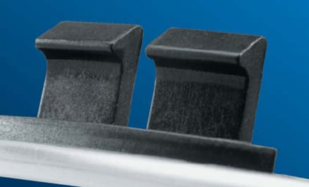
As discussed in Part I of this series, “General Applications and Types,” several properties and characteristics of thermoplastics make them particularly well suited for snap-fit designs:
• High flexibility compared with metals
• Sufficient stiffness, relatively high elongation
• Good strength
• Low coefficient of friction
In addition, thermoplastics are ideal for integrative designs, permitting one-piece molding of complex geometries, which consolidates multiple parts into one. Part III of this series, “Improved Cantilever Design,” presented innovative formulas, which now enable the design engineer to develop and produce optimal snap-fit assemblies with plastics. Still, the ultimate success of any design also depends on selecting the material that best fulfills all requirements of a specific application.
The design engineer must weigh the relative importance of properties such as strength, stiffness and fatigue resistance, as well as the effects of factors such as temperature, moisture, friction and wear from repetitive assembly/disassembly cycles over time. To help design engineers begin the process of evaluating materials, this article discusses the properties most essential to the successful performance of plastics in snap-fit designs. And, it provides a comparative snapshot of the major resins that possess those properties.
IMPORTANT PROPERTIES
Even the best of snap-fit designs requires the support of a material with the right combination of properties for its application. Five properties have proven most important to success in the broadest range of snap-fit applications.
1. Modulus of Elasticity
Modulus affects the degree of stiffness or rigidity and determines firmness of the assembly. If the application demands that the snap-fit assembly conform to tighter tolerances, the design engineer will want a material with higher modulus – greater stiffness. If the application does not demand such tight tolerances, the designer can specify a material with lower modulus – more flexibility. The designer may also achieve some degree of economy with a material not developed for higher tolerances. However, in applications with more dynamic and repetitive demands, lower modulus could potentially result in more noise (or BSR: buzz, squeak and rattle) from loose joints. The tightness of an assembly with a higher modulus material also helps establish the “feel” of a product, in some cases contributing to a tangible sense of quality.
2. Tensile Elongation and Strength
If a snap-fit finger is deflected excessively, it will either break or undergo permanent deformation, and it will fail to hold the assembly together. The extent of such deflection before the snap-fit fails is determined by the material’s elongation limit of the material, and the greater the elongation the greater the allowable deflection (see box below).
Generally, low-strength materials exhibit higher elongation and high-strength materials lower elongation. On the other hand, for a given design, lower strength materials tend to have lower modulus and will produce loose assemblies, while higher strength materials exhibit higher modulus and produce tighter assemblies. However, the higher strength materials tend to exhibit lower elongation and therefore offer smaller allowable deflection limits for the snap-fit design. The design engineer can handle the conflicting requirements in two ways:
• Modify the snap-fit design length and cross sections to meet both stiffness and deflection requirements for the given material
• Choose a material that meets both stiffness requirements and deflection requirements for the given design
In most cases, a snap-fit design process is a trial and error process of material selection and design iterations. Knowing the limits of various materials’ elongation and tensile strength prepares engineers to ensure that their snap-fit assembly design exceeds requirements of the end-use application.
Tensile behavior of a plastic comprises two measures: stress and strain. Stress is expressed as a force (load) applied over a specified area, (psi or MPa). Strain is expressed as a percentage of change in length sustained under load. When load increases, stress on the plastic increases in response, until the material can no longer bear the applied load and it either gives (yields) or breaks. The maximum load under which the material can sustain its integrity without yielding or breaking is called ‘Tensile Strength’ of the material. Similarly, the material will increase its strain level under applied loads. The maximum strain value at which a material breaks is defined as the “Elongation” of the material.
3. Coefficient of Friction
The coefficient of friction contributes to how easy or difficult it is to assemble or disassemble a given snap-fit joint design. However, the coefficient of friction is determined not only by the natural lubricity of the material but also by the combination of other environmental factors such as temperature and humidity, smoothness of molded surfaces, the roughness of reinforced resins, as well as dirt, oil and other contaminants from real-world use. Therefore, it is difficult to assign an exact value for any given application. Often a design engineer must use an approximate value for a snap-fit calculation, based on individual experience with particular applications.
4. Fatigue Strength
Fatigue strength of a material is often expressed in terms of stress vs. cycles-to-failure curves. It tells the design engineer about the ability of a material to withstand a given level of repetitive loading (or cyclic stress) until the point of failure from fatigue – number of cycles until breaking. The fatigue curves are normally developed at a standard frequency of loading cycles, depending on the test specifications. However, the fatigue behavior can change depending on the test speeds (or frequencies), temperatures and moisture conditions (as in the case of a polyamide material). Therefore, a design engineer needs to select a curve that approximates real-world application conditions. Unlike for metals, there is no infinite life for plastics; the fatigue curve never becomes flat (horizontal). The curve continues to slope down, but at a slower rate. A common practice is to pick a stress level of 10E6 or 10E7 cycles to failure as a typical fatigue strength of a plastics material. Depending on how critical failure of the snap-fit assembly is, the design engineer can be either more or less conservative in calculating a safe part lifecycle.
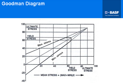
Another important factor to consider is the type of loading. Standard fatigue tests are conducted with fully reversed cyclic loading, i.e., a cycle from fully tensile stress to fully compressive stress – or fully reversed cyclic loading. In application, however, most snap-fit products do not experience fully reversed loading: one side of the snap finger cycles from zero stress to maximum tensile stress; and the other side, only from zero to maximum compressive stress. This typical situation exhibits less severe loading than the fully reversed load scenario that most fatigue curves are based on. Therefore, the design engineer must make an appropriate adjustment, such as a Goodman diagram approach (see graph below), to determine a more realistic life expectancy for the snap finger.
A Goodman Diagram of a Plastic Material
5. Creep Behavior and Stress Relaxation
Creep:
Measures of creep behavior describe the deformation of a material under a constant load over time – counted as duration under a specific load at specific conditions, such as temperature and normally 50% relative humidity environment. Unlike elastic deformation, creep deformation generally is not recoverable. Creep behavior of a material informs the design engineer about the material’s ability to return to original geometry after loads and what degree of change from original geometry can occur. Snap-fit cantilevers normally undergo elastic deformation during assembly and return to their stress-free state afterward. Therefore, the creep property of a plastic material may not be such an important factor in plastics snap-fit design.
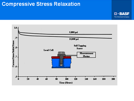
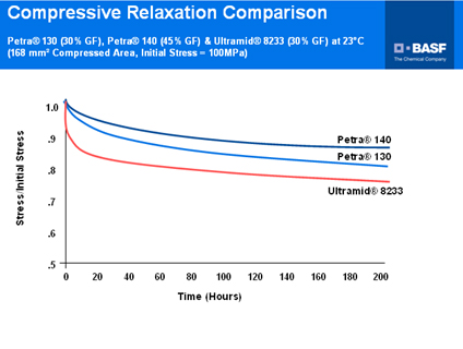
Stress Relaxation:
When seeking tightness of assembly, the engineer may design the snap finger as partially deflected so that it can exert enough axial force to pull two mating parts together. However, the assembly force will gradually decrease with time, and the tightness of assembly will decrease accordingly – caused by the stress relaxation behavior of plastic materials. One can predict assembly force based on the ‘stress-relaxation’ property of a plastics material. Conducting a stress relaxation test on the plastic material allows prediction of the amount of tightness decay: apply different levels of constant deformations to the plastic specimen and monitor the stress decay over time. The resulting stress relaxation curves (see graphs below) enable a realistic estimate of assembly force during the snap-fit assembly’s service life.
Stress Relaxation Curves
Normally it is easier to obtain the creep behavior than the stress relaxation behavior of a material. When an estimate of a material’s relative stress relaxation performance is unavailable, the relative creep behavior of the material may be used as a guide instead: A material prone to higher creep exhibits faster stress relaxation behavior.
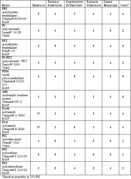
TYPICAL PROPERTIES OF MAJOR MATERIALS
Obviously, it is impossible in the scope of this article to provide a comprehensive analysis of thermoplastics whose properties and application histories qualify them as likely candidates for snap-fit design. However, the two tables accompanying this article introduce representative grades from the major resin families and provide a rough, rule-of-thumb rating of relative performance. For these tables, we have selected 30% glass fiber reinforced grades – unless otherwise noted – as starting points on the product paths you may wish to pursue further.
In thermoplastics families where BASF manufactures products, we have cited our own brands. In other categories, we have selected the product of a typical manufacturer. IDES maintains a library of datasheets for more than 75,000 different grades of thermoplastic resins. All performance information is from datasheets found on UL IDES Prospector Plastic Database.
 CONCLUSION
Prior to actual processing of snap-fit assemblies, design engineering and material selection are the two key factors. Parts I, II and III have introduced readers to the subject of snap-fit design, provided a historical perspective on design issues, and presented new theories and formulas that enable more accurate calculation of forces and more reliable designs. Part IV has now provided design engineers an overview of the thermoplastic resin properties most important to successful snap-fit performance – and a format to compare the differences between materials.
Part 1: Introduction and Overview of General Applications and Types
Part 2: Principles of Classical Beam Theory and Design
Part 3: Improved Cantilever Design and Guidelines to Avoid Common Difficulties
Part 4: Materials Selection
About the Author
| Chul Lee, Applications Technology Leader BASF Email: chul.lee@basf.com Website: http://www.basf.com/group/corporate/en/ |
Chul Lee, an Applications Technology Leader at BASF, has been involved with plastics applications and developmental activities for the past three decades. Working out of BASF Corporation’s Wyandotte, Michigan facility, Chul has a wealth of experience in various areas of plastics research, including service life prediction research for the plastics pipeline industry, and application of CAE technology for plastics product development. Chul’s current endeavors in the field are focused on the development of plastics joining technology, such as vibration welding, laserwelding and mechanical fastening.During the last 10 years, Chul has been actively involved in applications development work pertaining to the automotive and industrial market segments. Concentrating on application developments for the automotive powertrain market, including plastic air intake manifold developments and oil supply systems, Chul has coordinated BASF Global Research on Joining Technologies, such as vibration welding, laserwelding, snap fits, mechanical fastening and adhesive joining. Results of Mr. Lee’s research is often disseminated both internally and in the public domain by virtue of participation in seminars and publication distribution at major technical conferences.Chul, a Ph.D. graduate from the University of Michigan’s Mechanical Engineering department, has published many papers on various technical development topics. His academic specialization in the field of Fracture Behavior of Plastics Materials enables his astute research and subsequent publication of a multiplicity of topics, ranging from Snap Fit Design, Ribbing Design Optimization, Vibration welding optimization, and NVH (Noise Vibration and Harshness) experiments and simulations of air intake manifolds, and Laserwelding. Chul is also responsible for several patents, such as a patent on NVH, multiple patents on vibration welding, and currently has a patent pending on stone impact resistant ribbing design. |
The views, opinions and technical analyses presented here are those of the author or advertiser, and are not necessarily those of ULProspector.com or UL Solutions. The appearance of this content in the UL Prospector Knowledge Center does not constitute an endorsement by UL Solutions or its affiliates.
All content is subject to copyright and may not be reproduced without prior authorization from UL Solutions or the content author.
The content has been made available for informational and educational purposes only. While the editors of this site may verify the accuracy of its content from time to time, we assume no responsibility for errors made by the author, editorial staff or any other contributor.
UL Solutions does not make any representations or warranties with respect to the accuracy, applicability, fitness or completeness of the content. UL Solutions does not warrant the performance, effectiveness or applicability of sites listed or linked to in any content.