

Paid content by BASF
By Chul Lee, BASF
This is the 3rd article in a series of 5 articles by BASF Engineering Plastics on Snap-Fit design. The hope is to assist design engineers achieve better results using improved principles and procedures for snap-fit design, application, processing and fabrication.
PART 3: IMPROVING SNAP-FIT DESIGN: IMPROVED CANTILEVER DESIGN and GUIDELINES TO AVOID COMMON DIFFICULTIES
IMPROVED CANTILEVER DESIGN
The classical cantilever beam strain formulas discussed in Part II of “Improving Snap-Fit Design” work well when a flexible cantilever beam is anchored to a rigid wall, such as wood to stone. In such cases, deformation of the cantilever under a given load is the primary cause of movement at the tip of the cantilever. However, the typical plastic snap-fit design involves a snap-fit finger attached to a flexible wall – usually a plastics plate with thickness in the 3 mm range. When applied to these conventional plastic snap-fit designs, however, the classical formulas fail to account for the amount of deflection from the beam/wall interface. They simply neglect the effect of deformation in the wall itself – a factor that becomes more significant with somewhat more flexible wall materials, such as wood, composites and thermoplastics. The classical formula does predict deflection fairly well when a beam length-to-thickness ratio is greater than 10:1, but the calculated deflection deviates further from actual values as the ratio gets smaller or when the beam, in other words, gets “stubbier.”
To obtain a more accurate prediction of the total allowable deflection for short beams in snap-fits, the design engineer must apply a magnification factor to compensate for the classical formulas’ shortcomings. Doing so allows the design engineer to take full advantage of a material’s strain-carrying capability and, therefore, to enjoy greater design flexibility.
Magnification Factors
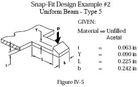
BASF Plastics has developed a method for determining these magnification factors for a variety of snap-fit beam/wall configurations, including beams with either uniform or tapered cross sections (graphically depicted in Figures IV-1 and IV-2).
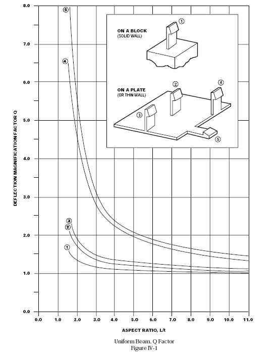
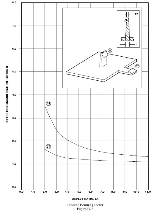
BASF has verified the results of this method both by finite element analysis and actual part testing.
 Improved Formulas
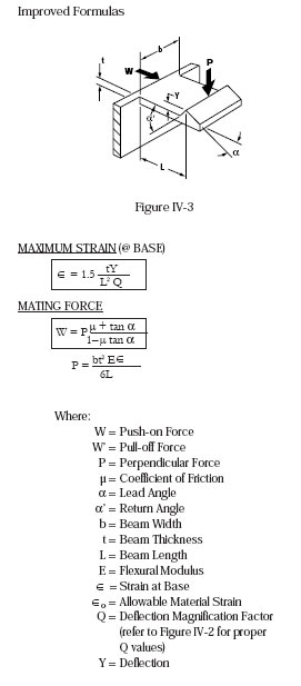
To determine maximum strain at a given snap-fit’s base, design engineers can now use the improved formula which incorporates a corrective magnification factor (See Figure IV-3). BASF also provides formulas for determining the Push-on and Perpendicular Mating Forces (Figure IV-3).
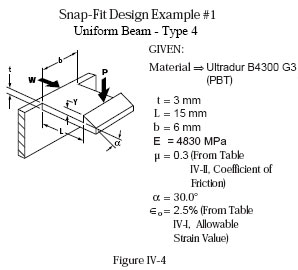
To review examples that employ these formulas to determine accurate solutions for two different snap-fit designs, see Figures IV-4 and IV-5. The first example incorporates allowable strain and coefficient of friction values for a specific grade of BASF Ultradur® PBT; the second example, for a grade of BASF Ultraform® POM. Refer to BASF’s Snap-Fit Design Manual Page IV-4 for tables providing allowable strain and coefficient of friction values for eight different materials appropriate for snap-fit designs.
U-shaped and L-shaped Designs
Design engineers interested in the application of these formulas to U-shaped and L-shaped snap-fit designs – and a more detailed discussion – can refer to BASF’s Snap-Fit Design Manual, Pages V-1, -2, -3 and -4.
Conclusion
The formulas developed by BASF represent a significant improvement over the classical cantilever beam deflection and strain formulas. Working with BASF’s improved formulas, design engineers can now more accurately calculate and predict the forces encountered – and allowable deflection limits – for different configurations of cantilever-type snap-fit assemblies. With the greater degree of certainty these formulas provide, design engineers can get the most of their materials and their designs.
GUIDELINES TO AVOID COMMON DIFFICULTIES
Before finalizing any snap-fit design, the design engineer should review three basic considerations:
• Stress Concentration
• Creep/Relaxation
• Fatigue
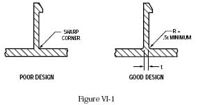 The single most common cause of failure in snap-fits is the concentration of stress caused by a sharp corner between the snap-fit beam and the wall to which it is attached – the normal point of maximum stress. One solution is to incorporate a generous fillet radius at the juncture between the beam and the wall, either on both sides of the beam or particularly on the beam’s tensile stress side (See Figure VI-1).
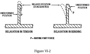
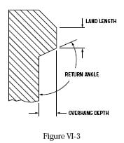
Another cause of failure is that, over time, creep and stress relaxation can gradually reduce the retention force between the two components connected by a snap-fit. In some cases, lower retention force can lead to leakage from a formerly tight seal; in others, excessive play that creates noise and vibration (or “BSR” – Buzz, Squeak and Rumble). Ways to minimize the effects of creep and stress relaxation include designing a low-stress snap beam, incorporating a 90° return angle to avoid bending, or increasing the land length in the area of a large return angle (See Figures VI-2 and VI-3).
The third major cause of snap-fit failure is fatigue, or repetitive loading, primarily in applications involving hundreds or thousands of cycles. The first, most obvious, way to avoid fatigue failure is to choose a material known to perform well in fatigue situations. Compare different materials’ S-N curves, which show expected number of cycles to failure at various stress levels and at different temperatures. A second way based on S-N curves is to select a sufficient design stress level at the application’s correct exposure temperature. In the real application, the frequency of cycles is usually a lower number than in testing, thereby providing a margin of safety for the design.
Conclusion
There are a number of ways to overcome stress concentration, stress relaxation or creep, and fatigue. A well thought-out design, plus the right choice of material, will allow your application to benefit from all the advantages of snap-fit design.
Materials Selection
Part 4 of the five-part series “Improving Snap-Fit Design” provides an overview of materials appropriate for snap-fit design and guidelines for selecting the material best suited to your applications. The complete series of articles includes:
Part 1: Introduction and Overview of General Applications and Types
Part 2: Principles of Classical Beam Theory and Design
Part 3: Improved Cantilever Design and Guidelines to Avoid Common Difficulties
Part 4: Materials Selection
About the Author
| Chul Lee, Applications Technology Leader BASF Email: chul.lee@basf.com Website: http://www.basf.com/group/corporate/en/ |
Chul Lee, an Applications Technology Leader at BASF, has been involved with plastics applications and developmental activities for the past three decades. Working out of BASF Corporation’s Wyandotte, Michigan facility, Chul has a wealth of experience in various areas of plastics research, including service life prediction research for the plastics pipeline industry, and application of CAE technology for plastics product development. Chul’s current endeavors in the field are focused on the development of plastics joining technology, such as vibration welding, laserwelding and mechanical fastening.During the last 10 years, Chul has been actively involved in applications development work pertaining to the automotive and industrial market segments. Concentrating on application developments for the automotive powertrain market, including plastic air intake manifold developments and oil supply systems, Chul has coordinated BASF Global Research on Joining Technologies, such as vibration welding, laserwelding, snap fits, mechanical fastening and adhesive joining. Results of Mr. Lee’s research is often disseminated both internally and in the public domain by virtue of participation in seminars and publication distribution at major technical conferences.Chul, a Ph.D. graduate from the University of Michigan’s Mechanical Engineering department, has published many papers on various technical development topics. His academic specialization in the field of Fracture Behavior of Plastics Materials enables his astute research and subsequent publication of a multiplicity of topics, ranging from Snap Fit Design, Ribbing Design Optimization, Vibration welding optimization, and NVH (Noise Vibration and Harshness) experiments and simulations of air intake manifolds, and Laserwelding. Chul is also responsible for several patents, such as a patent on NVH, multiple patents on vibration welding, and currently has a patent pending on stone impact resistant ribbing design. |
Search for plastics by material properties
With Prospector’s Property Search, search by properties to effectively and efficiently find the right plastics for your project.
Learn more
The views, opinions and technical analyses presented here are those of the author or advertiser, and are not necessarily those of ULProspector.com or UL Solutions. The appearance of this content in the UL Prospector Knowledge Center does not constitute an endorsement by UL Solutions or its affiliates.
All content is subject to copyright and may not be reproduced without prior authorization from UL Solutions or the content author.
The content has been made available for informational and educational purposes only. While the editors of this site may verify the accuracy of its content from time to time, we assume no responsibility for errors made by the author, editorial staff or any other contributor.
UL Solutions does not make any representations or warranties with respect to the accuracy, applicability, fitness or completeness of the content. UL Solutions does not warrant the performance, effectiveness or applicability of sites listed or linked to in any content.